Summary: This article will guide you through the basic steps to configure a point to point link using two 60 GHz cnWave V1000 nodes.
Product: 60 GHz cnWave V1000
Solution:
-
Check that the V1000 is connected to the power supply.
-
Connect the PC Ethernet port to the LAN port of the PSU.
-
Open a web browser and type the default IP address 169.254.1.1 in the address bar.
-
Enter an IP address that is valid for the 169.254.X.X/16 network, avoiding 169.254.1.1 (for example 169.254.1.3).
-
Enter a subnet mask of 255.255.0.0. Leave the default gateway blank.
-
When the login page will be prompted, type the default username and password as admin and admin. Click Sign In.
-
The Dashboard page appears as below:
-
Click the E2E Controller (last) option on the left pane of the Dashboard for Enabling the internal E2E Controller.


(The internal E2E controller is not required if you intend to tun the E2E controller On-Premise)

-
Click Enable E2E. The Enable Onboard E2E dialog box appears:
-
Enter the required details, enable Layer 2 Bridge (for IPv4 traffic), and click Enable.
-
After enabling the E2E Controller, add Sites, Nodes, and Links to establish the connection.
-
To add sites, nodes, and links, click Topology (2nd option) on the left navigation pane.
-
The POP DN site will be added by default after the onboard E2E controller is enabled and to add a CN site, click Add New. The Add Site dialog box appears, as shown below:

-
Enter the Name, Latitude, Longitude, Altitude, and Accuracy information, and click Save
-
Under the Nodes page, the DN node will be added by default and to add the CN node, click Add New and provide values in the Add Node dialog box, as shown below:


Map the node to its site from the Site drop-down menu in the above step.
For CN, the PoP Node has to be set as No and the Node type has to be selected as CN.
-
The CN node will appear in the Nodes tab as below mapped to its site:
-
To add a link, click on the Links tab on the Topology page.
-
Click Add New and provide values in the Add Link dialog box, as shown below:


Select the Link type wireless, A-node as PoP DN, and its MAC address from the drop-down menu Node-1 Wireless MAC. Then select the Z-Node as CN and its MAC address from the drop-down menu Node-2 Wireless MAC.
- Click Save. The new link gets added to the topology as shown below:

Once the link is formed, you will see the ignition attempts incrementing. Ensure the Ignition status is enabled, else click on the vertical three-dot menu and click on Enable Ignition.

-
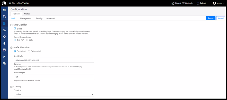
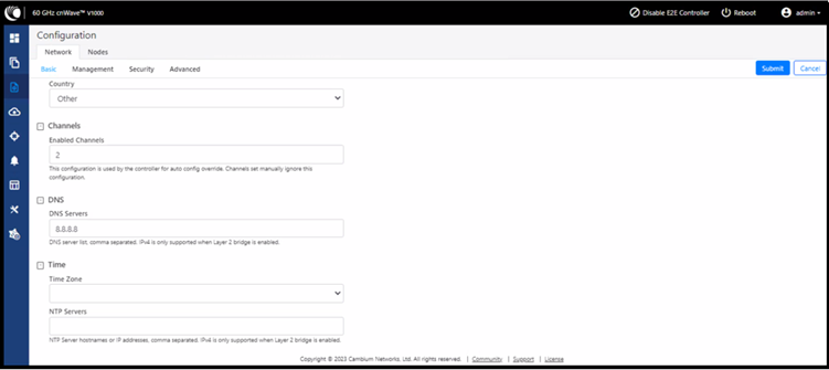
Under the Configuration>Network>Basic tab, ensure the Layer 2 Bridge is enabled for IPv4 traffic, select the country, enter DNS server details, and select the time zone/NTP server.
-
Under Configuration>Nodes tab, for a lab setup, set the Maximum EIRP to 13 dBm (minimum value) and IBF transmit power to Short Range (<25m). This has to be set to a maximum value of 38 dBm and Long range when sent out for deployment.

The adaptive modulation minimum and maximum values could be configured here.
For Channel and Polarity configurations, if the Override checkbox is not selected, the devices will automatically select the Channel and Polarity.
If you want to override the Channel or Polarity, checkmark the override box and choose the Node Config as per your requirement from the drop-down menu.
Note that the channels on POP DN and CN should match, while the polarity will be opposite.
If it is even at one end, at the other end it will be odd.
Similarly, the Golay should also match on both ends.

The CN node Radio configuration will be done by clicking on the CN node and then under the Radio tab following the same steps as above.

You will notice here the Channel is the same at both ends, however, the Polarity is the opposite.
Ensure that for the lab setup, this also has the Maximum EIRP set to 13 dBm (minimum) and IBF transmit power to Short Range (<25m).
The Golay on the POP DN and CN should be the same.

If the override checkbox is not selected, the Channel, Polarity, and Golay configurations will be taken care of automatically.
-
To configure the IP address, subnet mask, and gateway, click on the POP DN node under the Configuration>Nodes tab and go to Networking to enter these details.
-
To configure it on the CN, click on the CN node here under its Networking page, these details can be entered.
-
We can check and confirm on the Dashboard if the Layer 2 Bridge tunnel is formed:
-
Check the communication and if the traffic is passing by pinging the remote end (say 169.254.1.2):


