Summary:
How to connect the PMP450 radios physically in the lab environment.
Recommendations:
- It is recommended to place the AP and SM at a distance of 3 feet and both the radio faces should not point each other.
- It is recommended to connect the supported external antennas with the PMP450 Connectorized units. If the AP and SMs are connectorized unit then the pigtail cable can be used to connect both the radio units (wired connection between the radios). Cable layout diagram is shown below for reference.
- Connect the Ethernet cable between the first PMP450 ODU Ethernet (RJ45) port to the Cambium recommended PoE port (Data + out) and connect the PC Ethernet port to the LAN port of the PSU using a standard (not crossed) Ethernet cable.
- Follow the same connection (Refer above point) for second unit and do not connect both the radios to the same switch as it may cause a loop, for the link may not connect sometimes.
- Apply mains or battery power to the PSU. The green Power LED should illuminate continuously. After about several seconds, check that the orange Ethernet LED starts with 10 slow flashes.
- Check if the Ethernet LED illuminates continuously.
Configuration for AP and SM:
- Start the web browser from the management PC connected to the PoE port of the AP/SM.
- Configure an IP address on the laptop or management PC same as the 169.254.X.X network. Avoid 169.254.0.0 and 169.254.1.1. A good example is 169.254.1.3.
- Type the IP address of the unit into the address bar. The factory default IP address is 169.254.1.1. Press ENTER. The web interface menu and System Summary pages are displayed:
- On the left side of the home page, the login information is displayed as shown below. Enter Username (factory default username is admin) and Password (factory default password is admin) and click Login.

- Configure the below settings on both the radios to form a link and later we can configure other required settings.
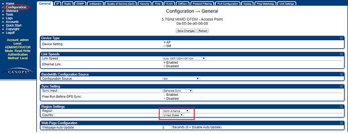
- Under AP UI>>>Configuration >> General >> Region Settings>>>Region and Country (See below screenshot).
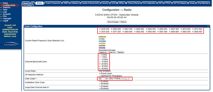
2. Under SM UI>>>Configuration >>Radio >>Radio configuration:-
- Frequency Band.
- Frequency Carrier.
- Channel Bandwidth.
- Color Code.
- Frame Size.
- Max Range: Enter the number of miles as per the maximum distance shown where a SM is allowed to register to this AP.
- TX power.
On the AP side:
On the SM side:
Note 1: All parameters 1-5 should be same on the subscriber unit. To avoid any damage to the radios in the lab due to high power, transmit power should not be more than 7 dB. Increase the TX power according to the regulatory limits when installed on field.
Note 2: Keep at least 60 dB of attenuation on each path (Horizontal and vertical) so that, the RF signal isn’t too strong.
Visit the below link to download the latest software version:
https://support.cambiumnetworks.com/files/pmp450/
How to check the link status on the AP and SM side:
- AP>>>Home page>>Session tab as shown below:
2. AP UI>>>Home page>>Remote subscribers tab as shown below:
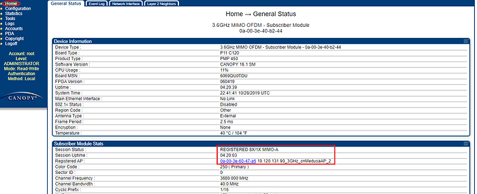
3. SM>>>Home page>>General tab as shown below:
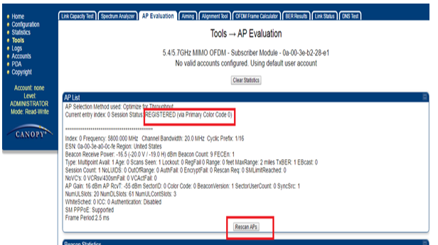
4. SM UI>>>Tools>>AP evaluation as shown below:

How to access the SM from the AP via proxy:
- Login to the AP UI and navigate to Home>>>Remote subscribers and click on the registered SM LUID:
2. Login to the AP UI and navigate to Home>>>Session status and click on the registered SM LUID:
How to access the SM from the AP using public IP:
- Login to the AP UI and navigate to Home>>>Remote subscribers and click on the registered SM LUID.
- To access the SM/BHS management interface from a device situated above the AP, the SM/BHS’s Network Accessibility parameter (under the web GUI at Configuration > IP) should be set to Public.
Note 1: The link will be formed between the PMP450 AP and PMP450 SM and not between two APs and two SMs.
Note 2: With the ICC feature enabled on the AP and SM, operators may install and remotely configure SMs without having to configure matching color codes between the modules. When using the Installation Color Code feature, ensure that the SM is configured with the factory default Color Code configuration (Color Code 1 is “0”, Color Code 2-10 set to “0” and “Disable”).
Note 3: It is recommended to keep the same software version of both the radios.


