Summary:
This document explains about the requirement and configuration required while configuring the Layer 3 VLAN on cnMatrix switch with DHCP server.
Cause:
Create a different LAN segment to reduce the broadcast domain with central DHCP management:
Topology:
I have considered the below network topology for this setup which is ideal for small and medium grade enterprises:
Note: I have considered VLAN 1 for connectivity between gateway device to cnMatrix switch as an example and considered 3 VLANs (50,100,150) for LAN connectivity. You can use any VLAN as per your Network requirement. NAT is configured on the gateway router for all outgoing traffic towards the internet.
** In the below network scenario, you need to configure the reverse static route for all the L3 network which belong/configured on cnMatrix switch at gateway router/Firewall to provide internet.
Example- IP ROUTE <Destination Address> <Destination SubnetMask> <Next hop>
IP ROUTE 192.168.100.0 255.255.255.0 1.1.1.3

Solution:
Please follow the below steps to configure the cnMatrix switch:
Step 1: Login to the web GUI of the cnMatrix switch using the IP address and Enter the Username and Password.
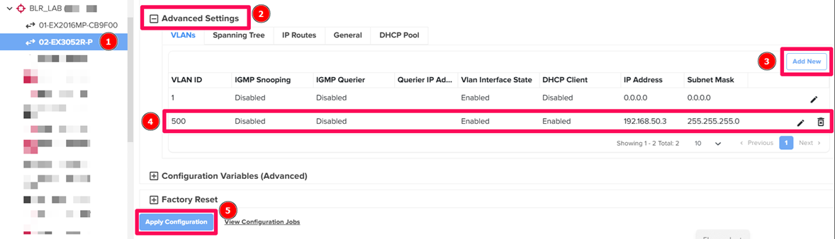
Step 2: Create Layer 3 VLAN Interface:
Click on Layer 3 Management >>> IP >>> VLAN interfaces enter VLAN ID and select Administrative State as UP in the drop-down menu as shown in the figure below:

** After creating respective VLAN, click the Apply.
Step 3: Configure the IP address on L3 VLAN interface:
Click on Layer 3 Management >>> IP >>> IPV4 Address Configuration select VLAN interface ID, IP Address Mode as Manual, enter IP Address, Subnet Mask and click on Modify as shown in the figure below:

Assign an IP address to other VLAN interfaces using the above method:

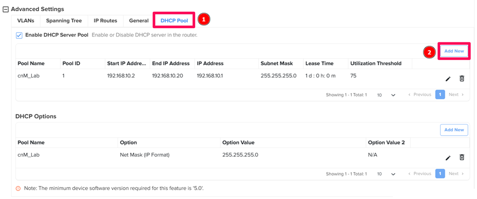
Step 4: Enable DHCP server:
Click on Layer 3 Management >>> DHCP Server >>> Basic Settings select DHCP server as Enabled then click on Apply button as shown in the figure below:

Step 5: Create DHCP Pool Settings for IP allocation:
Click on Layer 3 Management >>> DHCP Server >>> Pool Settings enter Pool ID, Pool Name, Subnet Pool as network address, Network Mask, Start IP Address, End IP Address and Lease Time in seconds then click on Add button as shown in the figure below:

Create DHCP Pool for other VLANs using the above step:

** After configuring respective DHCP Pool, click Apply button.
Step 6: Create DHCP Pool Options to configure the default gateway and DNS server with respective DHCP pool:
Click on Layer 3 Management >>> DHCP Server >>> Pool Options select Pool Name, Option as Default Router, enter Option Value as VLAN interface IP address and click on Add button as shown in the figure below:

Select Pool Name, Option as Domain Name Server, enter Option Value as DNS IP and click on Add button as shown in the figure below:

Configure the DNS and default router information for other DHCP pools:

** After configuring respective DHCP Pool Options, click Apply button.
Step 7: Create Layer 2 VLAN Interface and map it with the switch interface:
Click on Layer 2 Management >>> VLAN >>> Static VLANs enter VLAN ID, VLAN Name and Member Ports with Untagged Ports then click on Add button as shown in the figure below:

Also in the same page remove the desired port from VLAN 1 (Member Ports and Untagged Ports).
Configure the other VLAN and port membership using the above method:

** After configuring respective VLAN and interface, click the Apply button.
Step 8: Assign PVID on switch interface for untagged traffic:
Click on Layer 2 Management >>> VLAN >>> Port Settings select respective interface, enter VLAN no. in PVID section, select Acceptable Frame Type as “Untagged and Priority Tagged” and Click Apply button as shown in the figure below:

Step 9: Configure Access port on switch interface:
Click on Layer 2 Management >>> Port Manager >>> Basic Settings select respective interface, select Switch Port Mode as “Access” and Click Apply button as shown in the figure below:

Results: In this case, once the ethernet client connects with the desired Port, it will then become a member of the respective VLAN and will get an IP address dynamically from respective DHCP Pool. Be aware that a defaulted CNMatrix switch will also get an IP address from the corresponding pool (DHCP is enabled by default on VLAN 1) when connected to the DHCP server.
You can extend the network using L2 switch without making any additional configuration on L2 switches.
Note: Ensure that the Switch is on the latest version. You can check or download the latest cnMatrix switches from below Links: