LINKPlanner online has been updated to version 6.2.0
The key features of the 6.2.0 release are:
PTP 850/820
- Added 2+0 Co-Polar (ACCP), 2+0 Cross-Polar (ACAP), 2+0 XPIC (CCDP) Link Type for the following licensed band PTP 850/820 products.
- PTP 850C
- PTP 850E
- PTP 820C
- PTP 820S
- PTP 820G with RFU-C

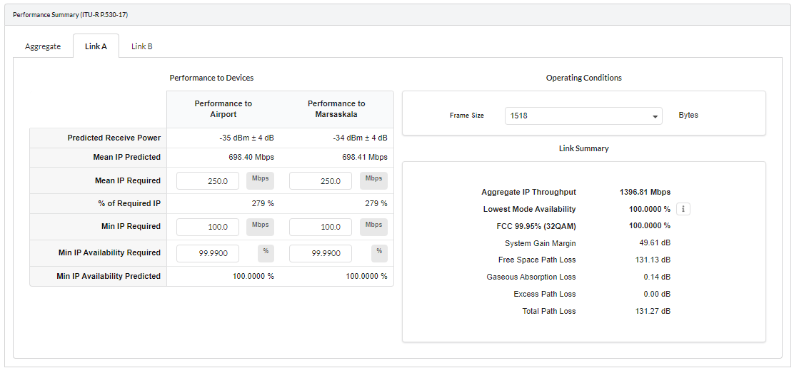
Parameters on each radio which can be different on each link are shown in a tabbed area of the Configuration at Each End panel. The Performance Summary and Performance Details also have tabbed sections to show the Aggregate, Link A and Link B parameters, as the required throughput and availability can be set differently for each path. The Performance Summary and Performance Details will always have the same tab selected.

- Retired PTP 820C in U6 GHz band.
- Retired PTP 820C HP in 11 GHz band.
ePMP
- ePMP 11ax updates
- Added support for ePMP 4500, ePMP 4500L, ePMP Force 4525, ePMP Force 4525L, Force 400C and Force 425 products to the PMP side.
- Added support for ePMP 4600, ePMP 4600L, ePMP Force 4625, ePMP Force 4600C products to the PMP side.
- Added TDD support for ePMP 4500/4600 products in PTP mode.
- Updated Transmit Power levels for ePMP Force 400C, ePMP Force 425, ePMP 4500L, ePMP Force 4525, ePMP Force 4525L, ePMP Force 4600C
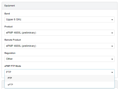
To use the 4600 family of radios, choose the Lower and Upper 6 GHz frequency bands
To use the 4500 family of radios, choose the 4.9 to 5.9 GHz frequency bands
“PTP” ePMP PTP Mode added for the ePMP 4500/4600 products in PTP mode. Now both “ePTP” and “PTP” ePMP PTP Mode are supported. This also includes the Force 400C and Force 425.
The maximum power in some bands and bandwidths has reduced by 1 or 2 dB to 28 dBm.
- Retired 2.4 GHz ePMP 1000 product.
PMP 450
- Added initial support for PMP 450v 4x4 ND and SM product to the PMP side of the LINKPlanner, using existing single carrier functionality. Carrier aggregation will be added in future releases.
PMP 450v can be selected as an ND in frequency bands 5.1, 5.2, 5.4, 5.8, Lower 6 GHz and Upper 6 GHz. It is backwards compatible with the rest of the 450 family, hence any 450 SM can be used with a 450v ND if the SM is supported in the frequency band and 450v SMs can be added to any 450 family ND.
Advanced Features
- Added Terragraph Planner advanced feature to automatically plan 60 GHz cnWave networks.
Use the Terragraph Planner feature to automatically plan a 60 GHz Network. The Terragraph Planner automatically selects the most appropriate DN locations, assigns the orientation of the DN and if required connects the CNs to each DN.
Please note that the Terragraph Planner requires Lidar data and therefore can only be used for networks where Lidar data is available.
To use Terragraph Planner feature, click on ![]() or
or ![]() under advanced features in the left hand Navigation Tree. Select the type of network plan required and proceed to the next sections.
under advanced features in the left hand Navigation Tree. Select the type of network plan required and proceed to the next sections.
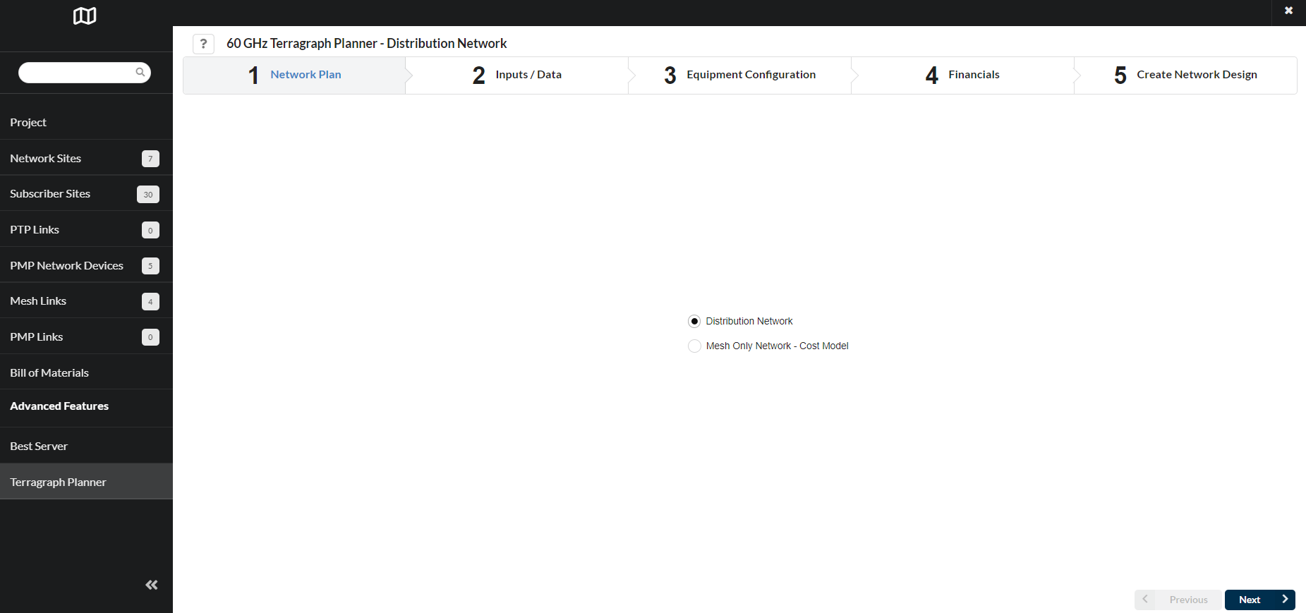
There are two approaches available to automatically plan the network:
- Distribution Network – End to End network planning with CNs. The project file must include both Network Sites and Subscriber Sites
- Mesh Only Network - Cost Model – 60 GHz backhaul network planning without CNs. The project file must include Network sites and does not require subscriber sites to be created. Any subscriber sites added to the project file will not be used in the analysis.
For more details, please refer to Terragraph Planner Configuration section under the user guide.
Viewshed
- Added High Resolution Viewshed feature which uses lidar data if available for the region
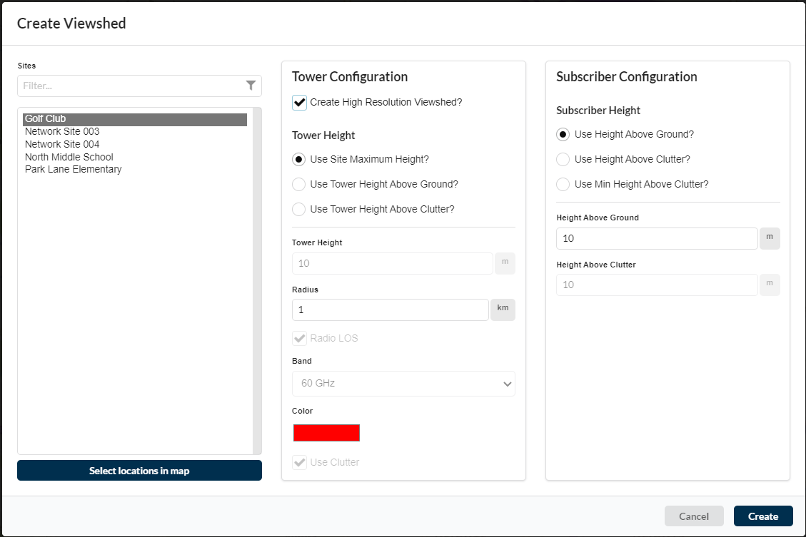
Tick Create High Resolution Viewshed? Box under the Viewshed configuration window, to create a High Resolution Viewshed for 60 GHz. This requires Lidar data to be available for the area.
cnWave 5G Fixed
- Updated sensitivity levels for cnWave 5G Fixed to Release 3.1.1.
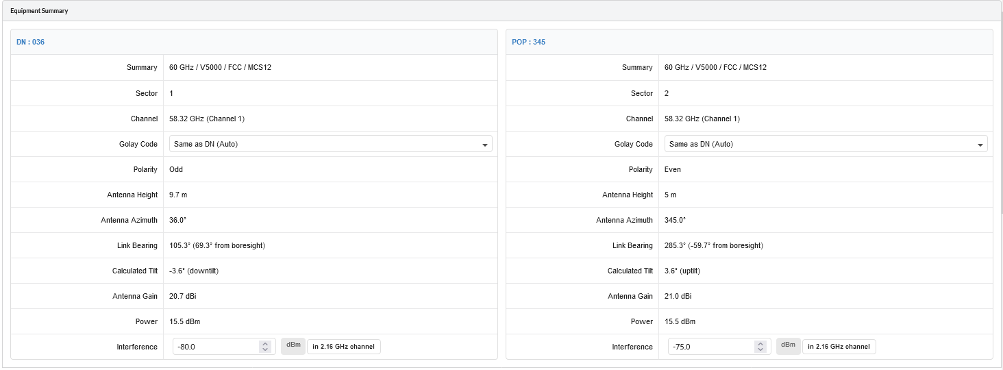
60 GHz cnWave
- Included interference field on the mesh link panel when interference levels are set on DN. Interference levels can now be adjusted on the individual mesh links.
Now interference levels are shown on the mesh links when interference levels are set on the DN. The default interference levels on the mesh links are the same as the interference levels of the DN, but they can be edited on the individual mesh links to give different levels for each mesh link.
General
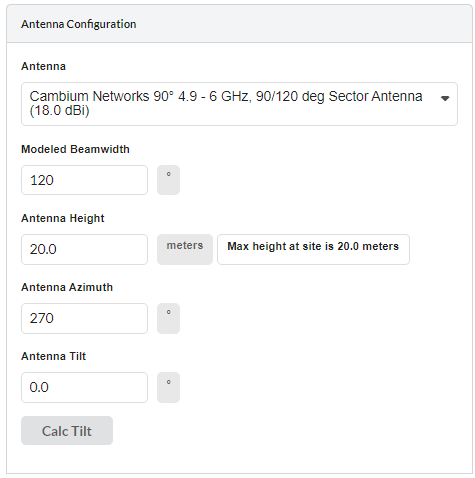
- Added Calc Tilt feature for the PMP Network Device.
Click Calc Tilt button under Antenna Configuration of ND properties to calculate the optimum mechanical tilt angle for maximum throughput.
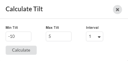
Select the Min and Max Tilt ranges and Interval step to run the feature.
When the calculation has finished running, the results are shown below the configuration settings. The angle that offers the maximum throughput has its radio button activated and is automatically selected. If multiple angles offer the same throughput then the middle angle is selected. To use a different angle, select the radio button next to the required row.
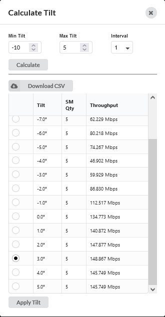
Please attach all the required subscriber modules to the Network Device before running this command.
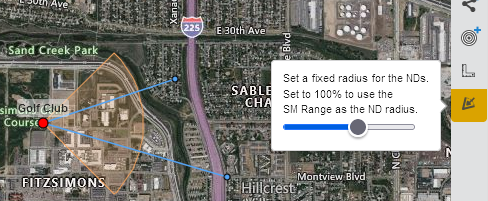
- Added ability to scale the display size of the PMP ND sectors on the map without affecting SM Range connectivity.
To change the displayed size of the Network Device sectors on the map, click and then adjust the slider to change the displayed size of the PMP sectors in the map view. This does not change the SM Range or the valid range for attaching subscribers, but makes it easier to see individual sectors when the full size view has overlapping sectors. When the scaling is active the sector display icon will be highlighted in yellow.
- Added Reflection Editor capability on path profile for PTP Links
Tick Enable Reflection Mitigation box to see the path profile to enable the calculation and display a visualization of the reflection on the Profile chart of the PTP Links.

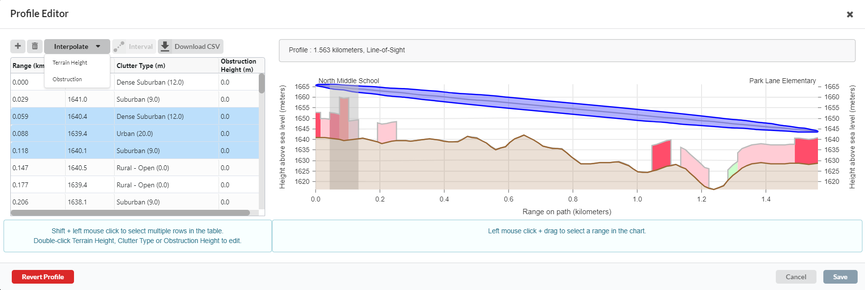
- Added interpolating heights or obstructions in a given range and inserting points in a defined interval along the path features to the path profile editor.
To adjust the heights for multiple points so that there is a constant gradient, set the heights at
either end of the range, then select the range and click the Interpolate button and select Terrain Height for Terrain Height adjustment or Obstruction for Obstruction Height adjustment.
If you are on a short link (< 300m) the resolution of the terrain and clutter data may be too coarse to show all the detail you wish to include. To add multiple points select the Interval button, then choose the point interval for the new points from the available list. The profile will then automatically have new points at the interval chosen with the terrain height interpolated between the known points.
- Displaying warning to the user if LINKPlanner truncating long names while importing the project
Users are warned if LINKPlanner project file contains long names or description while importing.
Bug Fixes
- Removed Tolly Mix frame size option for PTP 850E.
- Corrected PTP 850E throughput values to show Layer 2 the same as the other products, rather than Layer 1.
- Corrected Canadian compliance of 11 GHz Cambium Networks 4ft C1000082D049 antenna
Corrected Canada SRSP compliance to 310.7B from 310.7A for this antenna.
- Corrected PMP 450 family sensitivity levels for MIMO-A modulation modes
This increases the sensitivity of the MIMO-A mode by 3 dB relative to the equivalent MIMO-B mode. The MIMO-A modes have a very low probability of being used unless the path has high excess path loss, hence this change will not affect the majority of predictions, but on difficult paths will increase the availability of the MIMO-A modes. The lowest QPSK MIMO-A (x1) mode is not changed.
- Fixed the issue of PMP add Network Devices wizard failing for the ePMP product selection.
- Corrected “Right Height” column name in PTP table view.
- Fixed a bug preventing the Site CSV file from importing without the optional fields.
- Ensured that projects with missing profiles import without errors.
- Ensured that correct proposal and installation reports are produced for the mesh link selected.
- Default the Maximum Mod Mode to the highest mode when changing the product.
- Fixed issue with the path profile display when the height units are in “feet”.
- Ensured that warning messages are updating correctly in Create PTP Links dialog.
- Prevent very long PTP links from being created in the map
