Could you please confirm to me if the PTP 670 is compatible with the cnPulse Sync Generator?
I have done a several tests using cnPluse Sync Generator and it was not successful. What i have done so far is;
PTP 670 powered by it’s own PSU and using the AUX port to receive GPS Sync from a cnPulse - Not successful!!
Powered cnPulse Sync Generator and PTP 670 powered through it. The TDD synchronization was Locked in green which i means the device is receiving GPS sync BUT i did not had any link registered with the slave.
I’m actually using the firmware 50670-02-70.
Grateful to advise accordingly about the solutions.
Thanks.
Cheers.
You’ve shown that the PTP 670 ODU can be synchronized using a cnPulse in line with the Main PSU input. That approach works electrically, but you do have to take steps to seal the different sized cable glands. If the ODU is showing “Locked” then we have to look elsewhere to see why the link is not establishing.
It is also possible to synchronize using a cnPulse connected at the Aux port, but this is a bit more complicated. First, you need to fit an RJ-45 termination (dongle) at the PIDU port of the cnPulse. This allows the ODU to generate PoE output at the Aux port. Second, connect the ODU port of the cnPulse to the Aux port of the ODU. Third, you need to turn on Aux power output on the ODU. Fourth, you need to select the Aux port as the input for Cambium Sync.
The idea here is that the PTP 670 ODU is powered by PoE at the Main PSU port as normal. The ODU powers the cnPulse over a cable connection between the PTP 670 Aux port and the cnPulse ODU port. To do this you need to enable PoE output from the PTP 670.
Normally, the PTP 670 won’t power a device at the Aux port unless it is detected as a PoE powered device. We make the cnPulse appear as a powered device by fitting the dongle at the PIDU port of the cnPulse. The dongle is a simple RJ-45 plug with the following circuit:
We have a kit (C000070L004A) containing a cnPulse, bracket, dongle and replacement cable gland for this application.
Well, i did a test as per your last suggestion.
Allow me to recap about what i have understood and what i have done accordingly.
I have mounted a RJ-45 Plug termination (dongle) with the pin 1 & 3 linked with a resistor (51k) and pin 2 & 6 with another resistor (51k) and the rest of the pins are not connected means cut off. as shown in the diagram below, that dongle is then connected to the PIDU port of the cnPulse only. Is that correct?
A patch cable is then connected between the ODU port of the cnPulse and the PTP670 AUX port.
Hence, from the PTP670 from the TDD Synchronization field i have set the followings;
TDD Sync Device = Cambium Sync Injector
Sync Input Port is = AUX
Sync Output = None (Aux can’t be selected at this stage)
Unfortunately the test was not successful and i believe technically that there is something wrong.
If we look at it and as per my understanding of the cnPulse, this device could do the following;
PIDU Port - Power input
ODU Port/Sync - Could power up and provide sync to a PTP/PMP radio.
AUX Port - Could provide sync to a PTP/PMP radio (AUX to AUX)
If we go back to what you’ve requested to perform is to connect the cnPulse ODU port (which is basically an output port) to the AUX port (which is also an output port for PoE) of the PTP670. Therefore, there are 2 output ports connected.
My question for the dongle is, should the rest of the pins (4,5 7,8 which is for power) connect somewhere? As this part of the circuit open.
I did not see where i could enable the PoE output from the PTP670 neither.
Kindly advise accordingly the way forward.
Thanks again for the support.
If this is successful, you should see a blue LED illuminated inside the cnPulse. You’ll have to leave one of the glands off to see this from the outside.
You are correct in what you’ve done with the dongle. Fit the two resistors and leave the rest of the pins unconnected. The resistors indicate to the PTP 670 that the cnPulse is a PoE Powered Device. This is part of the IEEE 802.3 standard, and it prevents a PoE power supply from applying power to a regular Ethernet interface.
Well, i had to upgrade the firmware of the PTP 670 to the latest version so that ho have the “PoE Output” option.
Afterwards, i did the test but unfortunately it does not work. The cnPulse do not light up at all. (i did power it up separately just to confirm that the device good and it is)
I have done a test also to confirm the output by powering up another radio/antenna from the PTP 670 and the radio/antenna powered up.
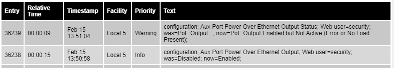
You previously showed that the ODU is able to generate PoE output at the Aux port by connecting another device. The syslog record suggests that there’s a problem with the wiring or the resistor network in the dongle. Can you try with the dongle connected directly to the PTP 670 Aux port?
Entry 852: PoE Output disable
Entry 853: PoE Enable
Entry 854: No Load connected
Entry 855: Load connected
Entry 856/857: Load disconnected
After connecting the dongle to the PTP 670, nothing detected at all.
My question is, does the cnPulse really work with the PTP 670 or not??
Hi Mark,
the resolution of this ticket is of tentamount importance to us. We have invested in 8 PTP670 radio that was initially cleared by Cambium to use Cn Pulse.
Now we are late in delivery by over two months and this is causing us enormous reputation damage.
Kindly revert back with some update and way to progress forward
This site is not the formal Cambium support channel. If this is urgent for you, you mustclick here to raise a support ticket. Although the Cambium team do often respond to questions on this site, there are no guarantees.
Raising a ticket ensures that your request is tracked by our customer support team, and won’t get ignored just because someone goes on holiday or anything like that.
Feel free to include a link to this thread in your ticket, so that the team can see what you’ve tried already.