LINKPlanner does not combine the throughput of the mesh links with the CN links and the total capacity for the CN side of the network still needs to be adjusted to allow space for the mesh link traffic. The throughput capability of the mesh links is now displayed at the DN level in the mesh table. The Performance Summary table for each DN continues to show the throughput allocated to the connected CNs.
First create a cnWave 60 GHz network layer, see How to channel plan a 60 GHz PMP network.
To add mesh links between two DNs either use the Offline map or select one of the ends.
Offline Map
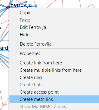
In the Offline map, right click on a DN site location and choose “Create mesh link” from the option list.
The map view will change to hide any other PTP or PMP links and only show the DNs, select the next DN to connect to the first and continue around the network linking DN sites together.
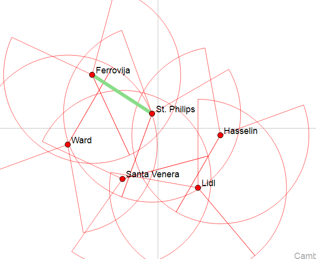
To start from a different DN location or to finish adding mesh links, click Esc or choose the “Select” arrow from the menu bar.
DN Equipment
In the DN Equipment window there is a new section called “Mesh Links”.

Select “Add Mesh Link” and then choose from the available links within range of the DN, select OK. The list of DNs offered are not constrained by the SM Range or the Modeled Beamwidth settings on the DN, but use a maximum range of 300 m and the full beamwidth of the DN.
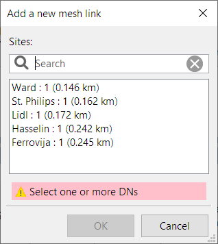
A total of four mesh links are allowed per DN, if more than four are selected a warning is shown. If more than 2 of the links are on the same sector then warnings are shown on the DN equipment. Remember to change the Max CN Registrations Allowed to leave space for the DN links on each sector.
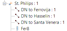
All the equipment settings for the mesh links are taken from the DN Equipment settings and cannot be changed on the mesh link. The DN links are shown in the list under each DN Node, using the PTP path symbol and a name starting with “DN to …”.
Mesh link parameters and performance
To see the equipment parameters and performance for a DN link, select it from the navigation tree. The equipment parameters are summarized for each end of the link. These are all shown as read only parameters unless the link is very close to the sector boundary, in which case the sector can be adjusted to use either sector. Note that changing the sector may change the antenna gain. The antenna gain is the gain of the DN antenna in the direction of the other end of the mesh link.

To change any of the equipment parameters go to the DN Equipment pane and make the changes there or use the Channel Plan feature to set the Channel, Golay Code and Polarity. Note that the same PTP rules for Channel, Golay Code and Polarity apply to the mesh links, where:
- Channel must be the same at each end of the link
- Golay Code must be the same at each end of the link
- Polarity must be opposite at each end of the link
If any of these rules are broken the mesh links will turn red. This is also shown when using the Channel Plan feature, so it can be good indicator when using the map view to set the values as to whether any are incompatible.
The other panels in this window are the same as for a PTP link. The profile can be edited in the usual manner, note that any changes to the ends of the link are only used on this mesh link and will not be used for other mesh or PMP links from the same end.
The key parameters of the mesh links are summarized in the Mesh Links panel on each DN and for the whole network in a new Mesh Links panel at the PMP Links level.

The values in these columns cannot be edited, but additional columns can be displayed and the order changed using the same methods as for the other table views in LINKPlanner.
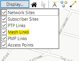
In the map view a mesh links option is now included in the Display tab, so the mesh links can be hidden from view if required, by unticking the box.
The Proposal report for each DN includes a Mesh Link Summary table and the usual PTP performance information is included in the DN Installation report for each mesh link. In a PMP level Installation report the mesh links are shown after the DNs in the index, rather than repeated under each DN.