The following process describes how to build a cnWave 60 GHz network with multiple hubs, Distribution Nodes (DN) and Client Nodes (CN). The DNs are represented in LINKPlanner as Access Points and the CNs as Subscriber Modules.
It assumes users know how to design a PMP network in LINKPlanner. For more information on the generic steps please go to http://linkplanner.cambiumnetworks.com/doc/getting_started.html
1. Add network sites from csv or kml.
For more information on adding sites see http://linkplanner.cambiumnetworks.com/doc/copying_or_importing_sites.html

cnWave 60 GHz Network Sites Added
2. Add subscriber sites from csv or kml.
For more information see http://linkplanner.cambiumnetworks.com/doc/copying_or_importing_sites.html

cnWave 60 GHz Network with Subscriber Sites Added
3. Create a cnWave 60 GHz PMP Equipment Template.
For more information on templates see http://community.cambiumnetworks.com/t5/LINKPlanner/Equipment-Templates-updated-to-include-SMs/td-p/49119
cnWave uses the same LINKPlanner structure as other PMP products with the DN functionality mapping onto an Access Point.
Configure the Access Point Equipment. Start by setting the band to 60 GHz and then choosing the Country from the list.
The V5000 consists of two sectors and the equipment configuration section is duplicated. Configure the parameters on each sector. Some parameters like the EIRP and Modulation Mode are common to both sectors.
The CN Capacity Limit allows throughput to be reserved for the mesh backhaul DN links. By default it is set to 100%, which will allow all the throughput of the sector to be used by the connected CNs. To reserve capacity on a sector for any DN to DN connections reduce the CN Capacity Limit.
To support DN to DN connections or to maintain higher throughput rates to the CNs reduce the Max CN Registrations Allowed.
The DN power is controlled by the EIRP level (which includes the antenna gain). Each sector will automatically show the maximum EIRP allowed by the product and the regulatory limit for the country. To reduce the EIRP tick the User Limit box and set the EIRP required.

cnWave 60 GHz DN Template settings
Select the default Client Node required in the Subscriber Module Equipment section.
Select the minimum required performance settings for the network and any optional extras required for all sites.

cnWave 60 GHz CN and Performance Template settings
4. Add hub sites and access points.
For more information on adding hubs see http://linkplanner.cambiumnetworks.com/doc/hubs.html
To create a new Hub, either click Project, New Hub or click New Hub . The New Hub page is displayed.

cnWave Add New Hub entry window
For cnWave 60 GHz networks the hub sites typically only have one DN per site, unless it is a very dense network or multiple frequency layers are required. Select OK to add the sectors to the hub sites.

cnWave 60 GHz Network with Hubs and Access Points
5. Adjust the orientation of the DNs
To cover the CN locations adjust the orientation of the DNs by selecting the sector coverage area and dragging the center point to the orientation and range required.
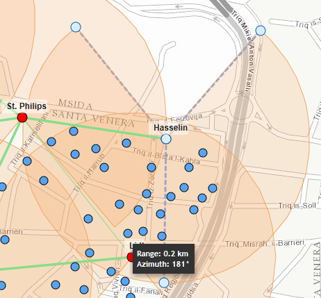
Change sector orientation and range

cnWave 60 GHz Network with updated DN orientations
6. Connect subscribers using Best Server Analysis.
For more information on the Best Server Analysis function see http://linkplanner.cambiumnetworks.com/doc/best_server_analysis.html

cnWave 60 GHz Network Connected
7. Sector specific parameters
The DN has other parameters which are not included in the template as they may need to be different per site or per sector within the network. These include the Channel, Golay Code and Polarity. How these are configured will affect the interference within the network, which is not calculated in LINKPlanner.
To configure these attributes either go to the individual DN or to configure multiple DNs at the same time go to the PMP Links – Access Points view and set the appropriate columns to be visible. For more information on choosing the columns to be displayed see http://linkplanner.cambiumnetworks.com/doc/managing_lists.html#customizing-the-list

Access Points Table View
Please note that the Golay Code is an equivalent feature to the Color Code on other products and therefore in the Access Points table it is shown as Color Code.
If the Polarity is configured differently on sector 1 from sector 2 on a DN then the DN will be operating in Hybrid Mode and the throughput for each sector will be halved.
8. DN Performance
The Performance Summary section shows the Performance for each Sector individually and an Aggregate for both sectors combined. Select the tabs to show the different options.

Note: The throughput data shown here is for the connections to the CNs only and does not include any throughput on the DN to DN links.